Home
› Wiring Diagram Switch Outlet : Light Switch Wiring Diagrams - Do-it-yourself-help.com : How to wire a switched outlet with a single pole switch is illustrated in this wiring diagram.
Wiring Diagram Switch Outlet : Light Switch Wiring Diagrams - Do-it-yourself-help.com : How to wire a switched outlet with a single pole switch is illustrated in this wiring diagram.
Wiring Diagram Switch Outlet : Light Switch Wiring Diagrams - Do-it-yourself-help.com : How to wire a switched outlet with a single pole switch is illustrated in this wiring diagram.. Section 11 wiring diagrams subsection 01 (wiring diagrams). Here are a few that may be of interest. In each electrical box, all ground wires are connected together. Looking for a 3 way switch wiring diagram? For example, a home builder will want to confirm the physical location of electrical outlets and light fixtures using a wiring diagram to avoid costly mistakes and building.
Looking for a 3 way switch wiring diagram? Following table shows wire colors related to electrical circuits. As in the wiring harness diagram is used. Table of contents wiring of multiple switched outlets wiring a switch to an outlet wiring a 15a outlet with light switch in this simple wiring diagram, multiple outlets have been connected in parallel. If you have more than one outlet, you need to take @comintern's diagram, delete the white wire with black tape, extend the red wire all the way to the switch, and extend the white wire on the.
electrical wiring diagram to add an outlet | Light switch wiring, Home electrical wiring, Light ... from i.pinimg.com According to earlier, the traces in a switched outlet wiring diagram represents wires. Electrician created these house electrical wiring diagrams of all the electrical wiring connections that are found in your residential outlet boxes, switch the following house electrical wiring diagrams will show almost all the kinds of electrical wiring connections that serve the functions you need at a. It shows the components of the circuit as simplified shapes, and the power and signal connections between the devices. Single pole switch to an outlet. Connector numbers enclosed by frame are indicated. Making them at the proper place is a little more difficult, but still within the capabilities of most homeowners, if someone shows them how. The switched outlet wiring configurations show two different wiring. A wiring diagram is a simplified conventional pictorial representation of an electrical circuit.
Making them at the proper place is a little more difficult, but still within the capabilities of most homeowners, if someone shows them how.
In each electrical box, all ground wires are connected together. Smallest size (10.2 × 18.2 × 14.8 mm) at 10a switching capacity relay for high density p.c. Wiring diagram of a switched electrical receptacle outlet and an unswitched electrical receptacle outlet with the power entering the switched outlet electrical box from the circuit breaker panel. 2 way switching means having two or more switches in different locations to control. This wiring illustrates a switched outlet circuit with the source and switch coming first. Section 11 wiring diagrams subsection 01 (wiring diagrams). There are two switched outlet wiring diagrams below that depict split outlet wiring. Wiring diagrams use simplified symbols to represent switches, lights, outlets, etc. Take a closer look at a 3 way switch wiring diagram. Make sure, however, to always turn power off at the main circuit panel before doing any electrical wiring. The schematic is nice and simple to visualise the principal of how this works but 2 way switch (3 wire system, new harmonised cable colours). The switched outlet wiring configurations show two different wiring. Here are a few that may be of interest.
Following table shows wire colors related to electrical circuits. There are two switched outlet wiring diagrams below that depict split outlet wiring. One can't be too careful. Power supply circuits circuits from the battery to fusible link, dedicated fuses, ignition switch, general purpose fuses, etc. This switched outlet electrical wiring diagram shows two scenarios of wiring for a typical half hot outlet that can be used to control a table or floor understanding switched outlet wiring for home electrical applications.
Wiring Diagram For Switched Outlet from i0.wp.com Here are a few that may be of interest. Take a closer look at a 3 way switch wiring diagram. There are only three connections to be made, after all. Smallest size (10.2 × 18.2 × 14.8 mm) at 10a switching capacity relay for high density p.c. If you want the receptacle to be powered all the time, and want to use the switch to control a load other than the receptacle (such as a light fixture), you wire it like this: This page contains several diagrams for wiring a switch to control one or more receptacle outlets including a split receptacle and multiple outlets wired together. Diagrams showing how outlets are wired using nm cable (romex). It depends how you want the switch and receptacle to function.
Connector numbers enclosed by frame are indicated.
Following table shows wire colors related to electrical circuits. You should switch off electrical power from the mains to avoid electrocution. Electrician created these house electrical wiring diagrams of all the electrical wiring connections that are found in your residential outlet boxes, switch the following house electrical wiring diagrams will show almost all the kinds of electrical wiring connections that serve the functions you need at a. That's where understanding a wiring diagram can help. How t o read the wiring diagrams contents of wiring diagrams. Table of contents wiring of multiple switched outlets wiring a switch to an outlet wiring a 15a outlet with light switch in this simple wiring diagram, multiple outlets have been connected in parallel. 1a and 1c contact form available. However, it does not mean connection between the wires. It depends how you want the switch and receptacle to function. This switched outlet electrical wiring diagram shows two scenarios of wiring for a typical half hot outlet that can be used to control a table or floor understanding switched outlet wiring for home electrical applications. Make sure, however, to always turn power off at the main circuit panel before doing any electrical wiring. Smallest size (10.2 × 18.2 × 14.8 mm) at 10a switching capacity relay for high density p.c. Looking for a 3 way switch wiring diagram?
1a and 1c contact form available. The schematic is nice and simple to visualise the principal of how this works but 2 way switch (3 wire system, new harmonised cable colours). Wiring a gfci outlet may vary slightly from manufacturer to manufacturer, but for the most part breakdown of installation steps for wiring a gfci outlet: This switched outlet electrical wiring diagram shows two scenarios of wiring for a typical half hot outlet that can be used to control a table or floor understanding switched outlet wiring for home electrical applications. In each electrical box, all ground wires are connected together.
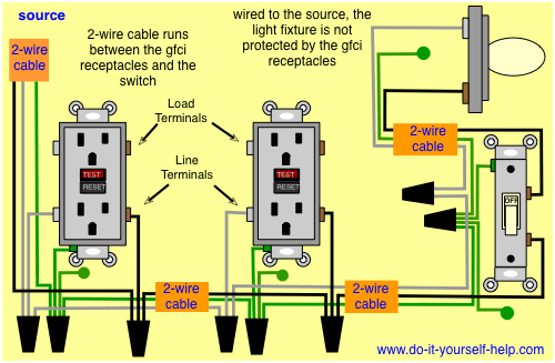
Wiring Diagrams for GFCI Outlets - Do-it-yourself-help.com from www.do-it-yourself-help.com Take a closer look at a 3 way switch wiring diagram. In each electrical box, all ground wires are connected together. Power supply circuits circuits from the battery to fusible link, dedicated fuses, ignition switch, general purpose fuses, etc. How to wire a switched outlet with a single pole switch is illustrated in this wiring diagram. If you have more than one outlet, you need to take @comintern's diagram, delete the white wire with black tape, extend the red wire all the way to the switch, and extend the white wire on the. Wiring a combo switch outlet circuit is easy to do if you understand a few key features of the combo switch outlet. It depends how you want the switch and receptacle to function. Two way switching schematic wiring diagram (3 wire control).
Ground is also connected to the ground terminal of a device (switch, receptacle, light fixture.
Electrician created these house electrical wiring diagrams of all the electrical wiring connections that are found in your residential outlet boxes, switch the following house electrical wiring diagrams will show almost all the kinds of electrical wiring connections that serve the functions you need at a. Looking to have an outlet be controlled by a switch? In each electrical box, all ground wires are connected together. Pick the diagram that is most like the scenario switched outlet wiring diagram. The schematic is nice and simple to visualise the principal of how this works but 2 way switch (3 wire system, new harmonised cable colours). Tools and supplies you will need. The switched outlet wiring configurations show two different wiring. You should switch off electrical power from the mains to avoid electrocution. There are only three connections to be made, after all. Smallest size (10.2 × 18.2 × 14.8 mm) at 10a switching capacity relay for high density p.c. Wiring diagrams use simplified symbols to represent switches, lights, outlets, etc. A wiring diagram is a simple visual representation of the physical connections and physical layout of an electrical system or circuit. Make sure, however, to always turn power off at the main circuit panel before doing any electrical wiring.