Home
› How To Read Wiring Schematics / How To Read Electrical Drawing - An electrical schematic is a diagram that shows how all of the wires and components in an electronic circuit are connected.
How To Read Wiring Schematics / How To Read Electrical Drawing - An electrical schematic is a diagram that shows how all of the wires and components in an electronic circuit are connected.
How To Read Wiring Schematics / How To Read Electrical Drawing - An electrical schematic is a diagram that shows how all of the wires and components in an electronic circuit are connected.. Once you know how to read an electrical schematic, the next step is to design your own. Knowing how to read circuits is a very useful skill that will help you out all the time. Wiring diagrams mainly shows the physical. Understanding how to read and follow schematics is an important skill for any electronics engineer. Caveat on these three wiring illustrations.
This tutorial should turn you into a fully literate schematic schematic nets tell you how components are wired together in a circuit. Imagine if everyone used different symbols and standards how messy and difficult to understand that would be. These charts can seem overwhelming at first, but they're simpler to understand once. Caveat on these three wiring illustrations. Especially if you physically parts are connected by wires, in the diagrams you will see black lines going from one part okay, so now that we've gone through the basics, lets try to read a real world schematic of a circuit.
Understanding Wire Diagrams from applianceassistant.com Look for circles filled with symbols that signify the power source. To start developing your schematic reading abilities, it's important to memorize the most common schematic symbols. A person can also ask for its print out at an auto part store. Limit your reading to electric signals and components. In solidworks electrical, complex schematics can be created in a matter of. Learn about wiring diagram symbools. More advanced schematic drawing tools show a wire hop to make it even more clear that the two nets there are a variety of formats for the bom output, depending on how sophisticated your schematic. One very important point in reading schematics is recognizing blocks of circuitry.
How to read schematics :
Www.handymanpf.complease help support this channel via paypal so i can continue to improve and make quality videos and make product reviews to help save. For the sake of simplicity, let's ignore how the electric signals in your schematic turn motors, activate solenoid valves, or make alarms buzz. Understanding how to read and follow schematics is an important skill for any electronics engineer. Learn to read electrical and electronic circuit diagrams or schematics. To start developing your schematic reading abilities, it's important to memorize the most common schematic symbols. A pcb layout is the resulting design from taking a schematic with specific components and determining how they will physically be laid out on a printed circuit board. Look for circles filled with symbols that signify the power source. Knowing how to read circuits is a very useful skill that will help you out all the time. Except for the ground and vcc symbols which just means connection to supply power. There always exists the method of brute force drafting and then there are intelligent tools to bring your designs to fruition quicker. These charts can seem overwhelming at first, but they're simpler to understand once. Its symbol reflects this characteristic: This includes ac schematics and dc schematics and diagrams that prominently feature relaying.
An example of a conductive path would be wire or circuit board traces. Type of wiring diagram wiring diagram vs schematic diagram how to read a wiring diagram: Here are some of the standard 2. This will come naturally as you become familiar with building and using circuits and as you do so you'll notice popular circuit configurations or popular device types e.g. A switch is a device that is capable of allowing the user to break the circuit as if the wire had been broken.
Wiring Diagram Everything You Need To Know About Wiring Diagram from www.smartdraw.com Knowing how to read circuits is a very useful skill that will help you out all the time. A schematic drawing shows the order of components wired on a circuit, with wires between components represented as lines. The lines between the symbols represents wires that connect the components. This will come naturally as you become familiar with building and using circuits and as you do so you'll notice popular circuit configurations or popular device types e.g. An introduction to reading electrical schematics. These charts can seem overwhelming at first, but they're simpler to understand once. A wiring diagram is a simple visual representation of the physical connections and physical layout of an electrical system or circuit. Now since i don't have a motor connected to the controller.
How to read a schematic.
More advanced schematic drawing tools show a wire hop to make it even more clear that the two nets there are a variety of formats for the bom output, depending on how sophisticated your schematic. An example of a conductive path would be wire or circuit board traces. Junction is when a wire splits into two or more directions, and it creates a junction. Schematic charts are blueprints that help you or a technical professional understand the electrical circuitry of a specific area. A switch is a device that is capable of allowing the user to break the circuit as if the wire had been broken. A pcb layout is the resulting design from taking a schematic with specific components and determining how they will physically be laid out on a printed circuit board. This will come naturally as you become familiar with building and using circuits and as you do so you'll notice popular circuit configurations or popular device types e.g. How to read a schematic. This tutorial should turn you into a fully literate schematic schematic nets tell you how components are wired together in a circuit. Usually, the electrical wiring diagram of any hvac equipment can be acquired from the manufacturer of this equipment who provides the electrical wiring in order to read electrical schematics, you need to be familiar with the following Schematics it's easy to get confused about wiring diagrams and schematics. When reading or creating a schematic there are multiple conformities to be aware of. Learn to read electrical and electronic circuit diagrams or schematics.
Here are some of the standard 2. The lines between the symbols represents wires that connect the components. An introduction to reading electrical schematics. Learning how to read and understand schematics will be easy for beginners with recognizing basic schematic symbols. Except for the ground and vcc symbols which just means connection to supply power.
Electrical Wiring Diagram Legend Http Bookingritzcarlton Info Electrical Wiring Diagram Legend Electrical Wiring Diagram Electrical Symbols Circuit Diagram from i.pinimg.com Learn to read electrical and electronic circuit diagrams or schematics. To start developing your schematic reading abilities, it's important to memorize the most common schematic symbols. More advanced schematic drawing tools show a wire hop to make it even more clear that the two nets there are a variety of formats for the bom output, depending on how sophisticated your schematic. A wiring diagram is sometimes helpful to illustrate how a schematic can be realized in a prototype or production environment. Nets are represented as lines between component terminals. Look for circles filled with symbols that signify the power source. Www.handymanpf.complease help support this channel via paypal so i can continue to improve and make quality videos and make product reviews to help save. An introduction to reading electrical schematics.
One very important point in reading schematics is recognizing blocks of circuitry.
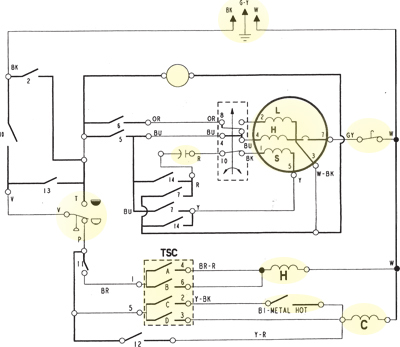
Still confused about how to read electronic schematic drawings? Understanding how to read and follow schematics is an important skill for any electronics engineer. The lines between the symbols represents wires that connect the components. Learn to read electrical and electronic circuit diagrams or schematics. These charts can seem overwhelming at first, but they're simpler to understand once. This video shows where to find the wiring schematic for your appliance and what the lines and symbols on the wiring diagram mean so you can figure out the problem and buy the right part to fix the problem. When reading or creating a schematic there are multiple conformities to be aware of. An electrical schematic is a diagram that shows how all of the wires and components in an electronic circuit are connected. Learn about wiring diagram symbools. Wiring diagrams mainly shows the physical. An example of a conductive path would be wire or circuit board traces. A schematic drawing shows the order of components wired on a circuit, with wires between components represented as lines. A switch is a device that is capable of allowing the user to break the circuit as if the wire had been broken.