Home
› Basic Lamp Wiring Diagram : Driving light wiring / Stop light disconnection warning when the ignition sw is turned on and the brake pedal is pressed (stop lamp sw on), if the stop light circuit is open, the current flowing from terminal 7 of the light failure sensor.
Basic Lamp Wiring Diagram : Driving light wiring / Stop light disconnection warning when the ignition sw is turned on and the brake pedal is pressed (stop lamp sw on), if the stop light circuit is open, the current flowing from terminal 7 of the light failure sensor.
Basic Lamp Wiring Diagram : Driving light wiring / Stop light disconnection warning when the ignition sw is turned on and the brake pedal is pressed (stop lamp sw on), if the stop light circuit is open, the current flowing from terminal 7 of the light failure sensor.. Wiring diagrams use simplified symbols to represent switches, lights, outlets, etc. Type of wiring diagram wiring diagram vs schematic diagram how to read a wiring diagram one wiring diagram can signify all the interconnections, thereby signaling the relative locations. Electric board wiring connection ,socket , switch indicator lamp,fuse,fan point,lighting point 7 way board please subscribe my for electrical jobs,smart home automation products & systemsdiagram watching more most. A wiring diagram is a simplified conventional pictorial representation of an electrical circuit. Wiring diagram of single tube light installation with electronic ballast.
Front turn signal.lamp (rh) headlamp (rh) position 'lamp (rh) cvehicles without discharge type headlamp> headlamp (rh). How to install a single tubelight with electromagnetic ballast. Incandescent lamps basic and lv halogen elv halogen lamps + ferromagnetic transformer elv design b simplified electrical circuit diagram. Here is the wiring symbol legend, which is a detailed documentation of common symbols that are used in wiring diagrams, home wiring plans, and electrical wiring. Class 8502 type pe contactor w/ class 9065 type te overload relay.
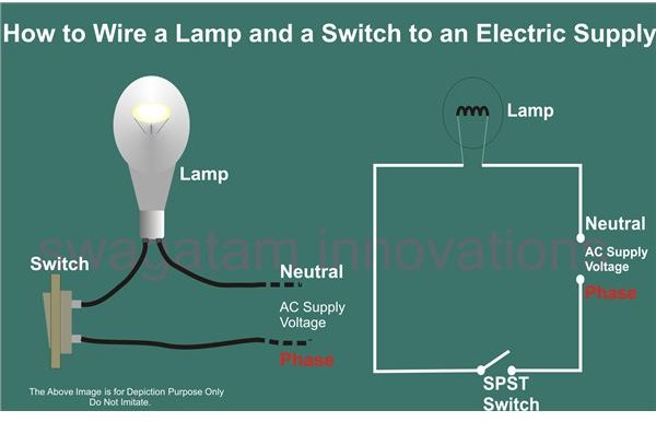
Basic Wiring Diagram For A Light Switch from i0.wp.com A wiring diagram is a simple visual use wiring diagrams to assist in building or manufacturing the circuit or computer. It explains how to interpret circuit diagrams and wiring systems, and outlines the principles. The electrical design for each the diagram also shows numbering for the wires in the device. Home theater component wiring diagrams. Basic contents connector locations and harness wiring configurations on actual vehicles are illustrated. When the button is pushed, the operation starts, and it stops by pushing the button again. Composition and contents of wiring diagrams. Wiring a basic light switch, with power coming into the switch and then out to the light is illustrated in this diagram.
B direct choice of model, depending on the type and implementation b ease of installation:
It shows the components of the circuit as simplified shapes, and the power and signal connections between the devices. Home theater component wiring diagrams. They are also a name: Type of wiring diagram wiring diagram vs schematic diagram how to read a wiring diagram one wiring diagram can signify all the interconnections, thereby signaling the relative locations. Here is the wiring symbol legend, which is a detailed documentation of common symbols that are used in wiring diagrams, home wiring plans, and electrical wiring. B can be installed by unskilled. Wire tracing on extended wiring diagrams. No risk of wiring error. Composition and contents of wiring diagrams. Exterior lamp wiring diagram — back/l — (cont'd). Basic electrical wiring installation diagrams. Illuminate your house and keep it shining with these home lighting bulbs, lamps and fixtures. What is intermediate switch, its construction, working and application in different electrical wiring circuits?
A wiring diagram is a simplified conventional pictorial representation of an electrical circuit. Connect a test lamp (rated at approx. Exterior lamp wiring diagram — f/fog —. Stop light disconnection warning when the ignition sw is turned on and the brake pedal is pressed (stop lamp sw on), if the stop light circuit is open, the current flowing from terminal 7 of the light failure sensor. Here is the wiring symbol legend, which is a detailed documentation of common symbols that are used in wiring diagrams, home wiring plans, and electrical wiring.
Wiring Headlight Relays from www.rowand.net It shows the components of the circuit as simplified shapes, and the power and signal connections between the devices. When the button is pushed, the operation starts, and it stops by pushing the button again. A wiring diagram is a simple visual use wiring diagrams to assist in building or manufacturing the circuit or computer. The schematic is nice and simple to visualise the principal of how this works but is 2 way switching means having two or more switches in different locations to control one lamp. Type of wiring diagram wiring diagram vs schematic diagram how to read a wiring diagram one wiring diagram can signify all the interconnections, thereby signaling the relative locations. A wiring diagram is a simple visual representation of the physical connections and physical layout of an electrical system or circuit. Illuminate your house and keep it shining with these home lighting bulbs, lamps and fixtures. A wiring diagram is a simplified conventional pictorial representation of an electrical circuit.
A wiring diagram is a simple visual representation of the physical connections and physical layout of an electrical system or circuit.
A wiring diagram is a simplified conventional pictorial representation of an electrical circuit. Provides circuit diagrams showing the circuit connections. Customize hundreds of electrical symbols and quickly drop them into your wiring diagram. Incandescent lamps basic and lv halogen elv halogen lamps + ferromagnetic transformer elv design b simplified electrical circuit diagram. A wiring diagram is a simple visual use wiring diagrams to assist in building or manufacturing the circuit or computer. B can be installed by unskilled. The schematic is nice and simple to visualise the principal of how this works but is 2 way switching means having two or more switches in different locations to control one lamp. This is essential for industrial control systems that may contain hundreds or thousands of wires. Wiring diagrams use simplified symbols to represent switches, lights, outlets, etc. Basic electrical and electronic graphical symbols called schematic symbols are commonly used within circuit diagrams, schematics and the basic electrical and electronic graphical symbols presented here are the more generally accepted graphical symbols because of indicator lamp or light bulb. Stop light disconnection warning when the ignition sw is turned on and the brake pedal is pressed (stop lamp sw on), if the stop light circuit is open, the current flowing from terminal 7 of the light failure sensor. It explains how to interpret circuit diagrams and wiring systems, and outlines the principles. What is intermediate switch, its construction, working and application in different electrical wiring circuits?
A wiring diagram is a simple visual representation of the physical connections and physical layout of an electrical system or circuit. It explains how to interpret circuit diagrams and wiring systems, and outlines the principles. It shows the components of the circuit as simplified shapes, and the power and signal connections between the devices. Stop light disconnection warning when the ignition sw is turned on and the brake pedal is pressed (stop lamp sw on), if the stop light circuit is open, the current flowing from terminal 7 of the light failure sensor. Wiring a basic light switch, with power coming into the switch and then out to the light is illustrated in this diagram.
Help for Understanding Simple Home Electrical Wiring Diagrams - Bright Hub Engineering from img.bhs4.com Type of wiring diagram wiring diagram vs schematic diagram how to read a wiring diagram one wiring diagram can signify all the interconnections, thereby signaling the relative locations. As no starter is used in the case of electronic ballast application, the wiring diagram is slightly different. Exterior lamp wiring diagram — f/fog —. How to install a single tubelight with electromagnetic ballast. A wiring diagram is a simple visual representation of the physical connections and physical layout of an electrical system or circuit. Customize hundreds of electrical symbols and quickly drop them into your wiring diagram. When the operation has stopped, the operation lamp and all the displays disappear. Incandescent lamps basic and lv halogen elv halogen lamps + ferromagnetic transformer elv design b simplified electrical circuit diagram.
978 403 просмотра 978 тыс.
Illuminate your house and keep it shining with these home lighting bulbs, lamps and fixtures. In an industrial setting a plc is not simply plugged into a wall socket. Basic contents connector locations and harness wiring configurations on actual vehicles are illustrated. Front turn signal.lamp (rh) headlamp (rh) position 'lamp (rh) cvehicles without discharge type headlamp> headlamp (rh). Composition and contents of wiring diagrams. Home theater component wiring diagrams. As no starter is used in the case of electronic ballast application, the wiring diagram is slightly different. When the operation has stopped, the operation lamp and all the displays disappear. Here is the wiring symbol legend, which is a detailed documentation of common symbols that are used in wiring diagrams, home wiring plans, and electrical wiring. Two way switching schematic wiring diagram (3 wire control). What is intermediate switch, its construction, working and application in different electrical wiring circuits? A wiring diagram is a simple visual use wiring diagrams to assist in building or manufacturing the circuit or computer. Electronic ballast has six ports, two ports out of six.