Stereo Vu Meter Circuit Diagram
These comparators compare the audio voltage signal with a reference voltage. By using this circuit, the level of the signal in the audio device can be displayed like a stereo system, the audio level of cd, etc.
Stereo sound level meter / stereo vu meter.
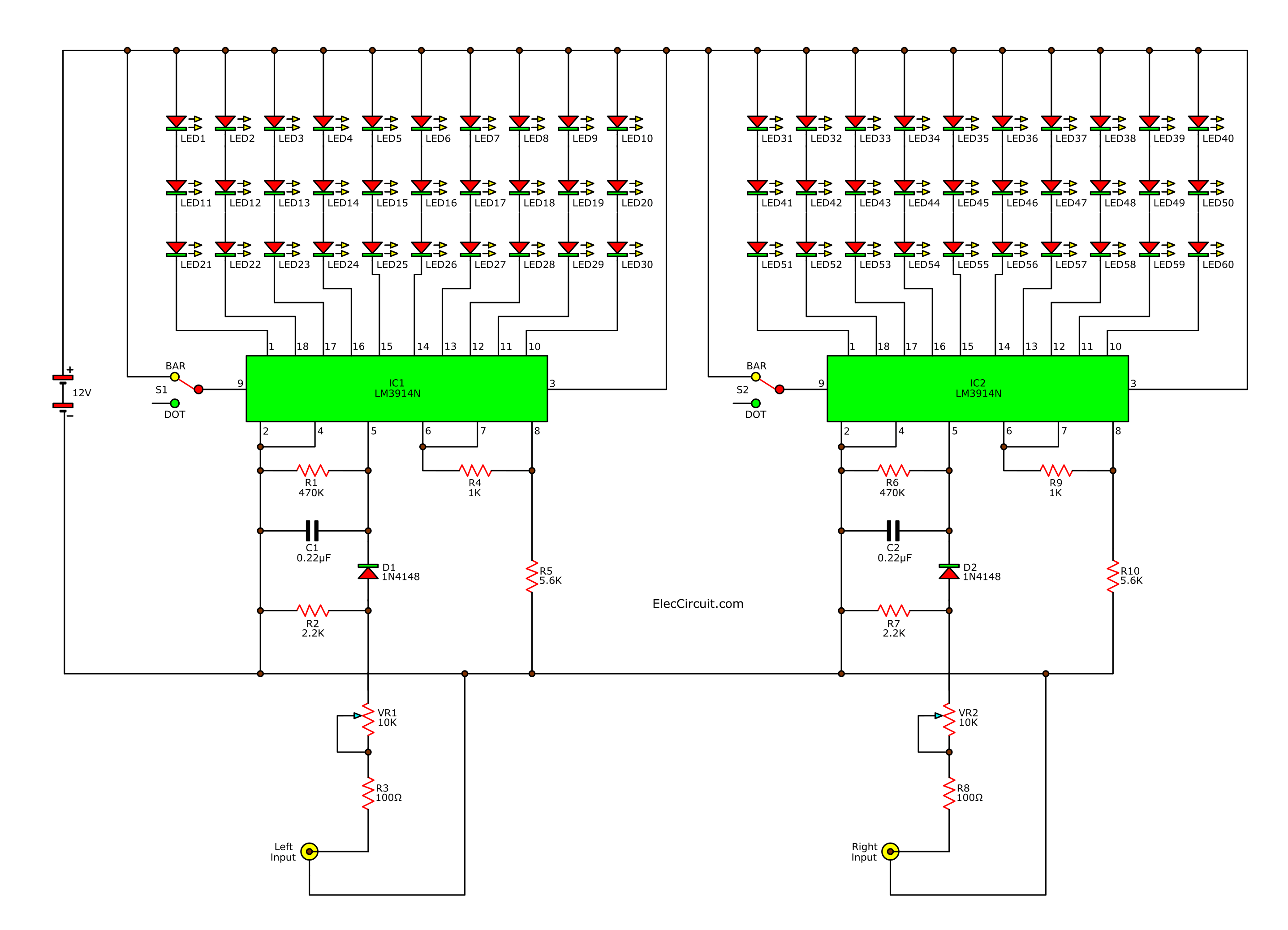
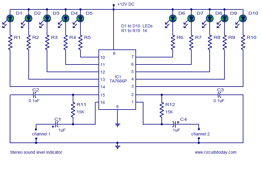
Stereo vu meter circuit diagram. It's basically a simple display for showing a value. It is a logarithmic display driver ic. The circuit shown here is of a stereo sound level indicator/vu meter using the ic ta7666p from toshiba.
Retro analog audio vu meter from scratch!: Vu meter circuit stereo/mono 20 led with pcb. Print out the above circuit diagram.
Vu meter 3 with lm3915 [10 led] s chematics wiring diagram circuits schema electronic. The values of these resistors are chosen to give a 5 db step between adjacent resistors. Read more… see the circuit below.
Electronic vu meter circuit diagram using lm3914 / lm3915. Each lower order led in the chain indicates 50% power or 70.71% voltage of the first higher led. This region uses an amplifier to produce an analog signal to drive 10 leds based on the audio signals.
This same vu meter was used in many other pieces of gear and broadcast consoles manufactured the 1970's and 1980's. A simple vu meter consists of a no. Input sensitivity is 100mv for a fsd on a 100ua ammeter.the circuit is build.
The circuit is for one channel input, if you need, for example 5 channel mixer, then you need to build 5 similar circuits. For stereo or for any other polyphonic version, the above block has to be repeated. Here are lm3914/lm3915 vu meter circuit projects.
Vu meter lm3915 driver integrated circuit used in 10 out there, according to the audio input volume with the. Ic1,2 = 741 or tl071. We will be happy when using them.
This 8 led vu meter circuit can be used to display the variation of an audio signal in a group of 8 leds, behaving like a vu meter. Where z is the loudspeaker impedance in ohms. I put together this voltage unit (vu) meter using leds on a breadboard the other day.
The series of audio level meter is also called a vu meter, but the vu meter is identical to the viewer in the form of a needle. The main of this circuit is lm3914n or lm3915. Also, we can easily build and cheap.
How to make stereo vu metercircuit diagram link: A dot mode and a bar graph mode. Lm3914n will display an amplitude of a signal in linear form.
It only has 4 leds, but can easily be expanded to more: The turn on levels for ta7666p are 5db, 5db, 3db, 3db and has a supply voltage range. Which the external circuit is the same.
The ka2284, ka2285 are monolithic integrated circuit. A simple vu meter consists of a no. The ta7666p consists of 2 inverting amplifiers, ten comparators and a reference voltage generator.
Lm3915n will display the signal in logarithm form. This circuit is absolutely works. P = u 2 / z.
If so, you are probably not using a vu meter. The vu meters indicate the amplitude of the incoming signals. A simple vu meter consists of a no.
Difference of lm3914 & lm3915. They can display with 20 leds on stereo or mono with 10 leds for all audio systems. This circuit uses an audio amplifier to generate an analog signal to drive 10 leds depending on the audio signals.
A simple and low cost audio level meter circuit that can be used to measure the audio level of your sound source.this circuit is a valuable tool for those who are interested in audio circuits. January 16, 2020 by øyvind nydal dahl 8 comments. This is an audio mixer circuit which designed along with vu meter circuit.
Below is a circuit diagram of a vu meter using the lm3914 integrated circuit. The circuit is designed with a flat frequency response in the range of 20hz to 50khz. The circuit diagram of the vu meter using lm3914 ic is shown below.
Using this region, the signal level at the audio device can be displayed such as stereo system, cd audio level, etc. I wanted to buy it, but i couldn't find one that was cool enough(and still reasonably priced) so i made my own.here i am going to shown you how i created this very cool looking stereo analog vu meter and i… The first stage is a precision rectifier.
Class a headphone amplifier circuit diagram read more. Lm3915, lm3914 vu meter circuit with've shared the printed circuit, but this circuit diagram is also drawn to separate mono and stereo vu meter circuit connection preanfil amps, amp direct connection drawn understood about the scheme. This circuit need about 18 vdc power supply to work, use regulated power supply for better performance.
The kit of this circuit is available on the market, i took the picture from electronic store in my town. Google passive vu and passive power meters use germanium diodes if possible because they have a much lower turn on voltage than any modern silicon type. I always wanted to have an analog vu meter.
Magic eye tube 6e2 em84 vu meter audio level indicator level circuit board adjustable sensitivity f/ amp signal amplifier. In this tutorial, i am going to discuss an audio vu meter circuit. It's originally for showing signal level in audio circuits, but there.
Here, we will make a circuit in a bar graph mode. The this audio mixer uses three potensiometers to adjust volume level, low frequency (bass) level and high frequency (treble)… read more » The meter shown in the diagram is based on eight opamps, contained in two type lm324 chips, which function as comparators.
vu meter circuit Page 3 Meter Counter Circuits Next.gr
STEREO_LED_VU_METER Measuring_and_Test_Circuit Circuit

Vu Meter Circuit Diagram Led Vu Meter Circuit Lm3915
Stereo audio vu meter circuit using KA2284
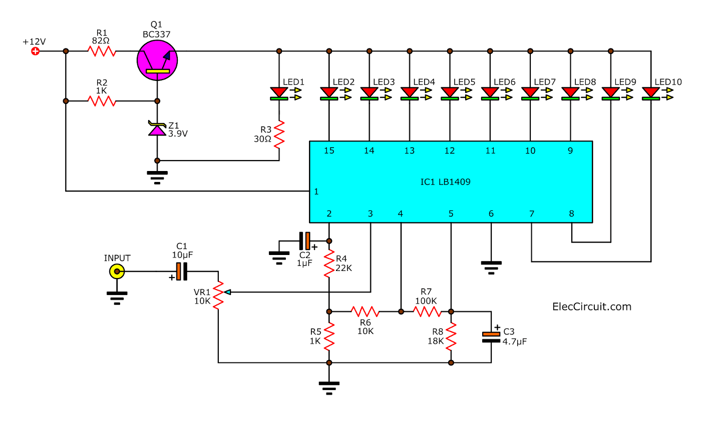
Sound level meter circuit using LB1409

Vu Meter 60 Db Lm3915 PCB Designs
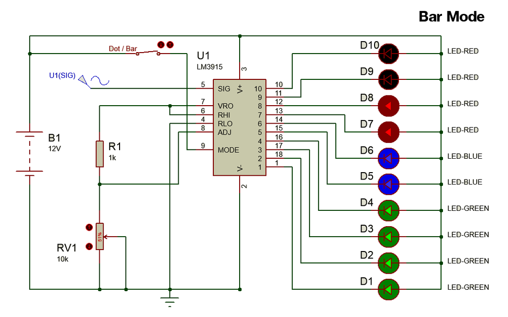
Lm3915 Vu Meter Circuit Diagram 40 Led Vu Meter With
how to make simple vu meter circuit at under Repository
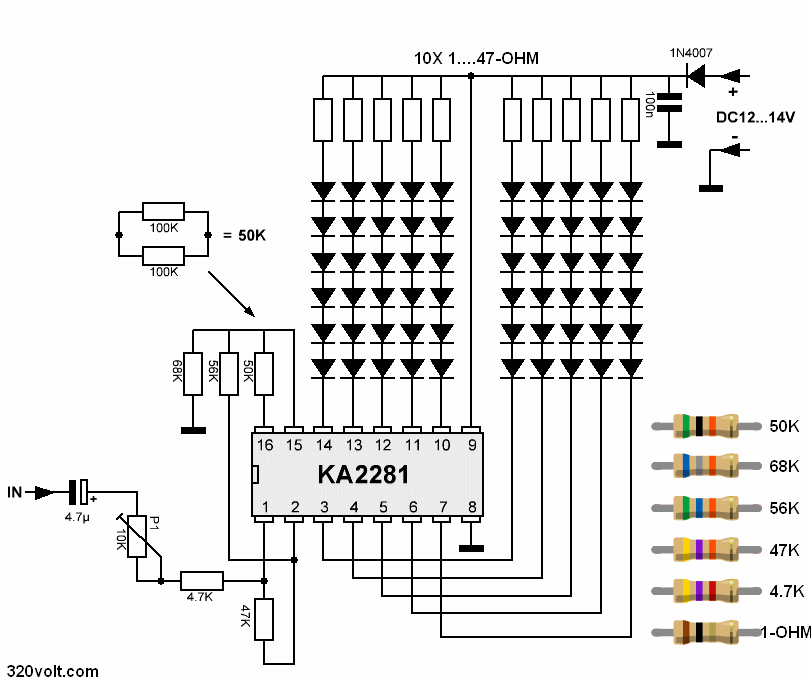
Stereo Vu Metre Devresi 120 Led KA2281 Elektronik
vu meter circuit Page 2 Meter Counter Circuits Next.gr

Wireless VU meter Using ATmega32A IC Full Electronics
Stereo VU meter 2 channel audio level meter

FAsT_ClicK Repair Shop Stereo LED Power (VU) Meter
Simple VU Meter Circuit Jeff Thompson

LEDVUmeterincrease Electronic Pinterest Audio


