Home
› Circuit Diagram Switch Board - Two Way Switch Wiring One Gang Two Way Switch And Multiway Switch : Easyeda is a free and easy to use circuit design, circuit simulator and pcb design that runs in your web browser.
Circuit Diagram Switch Board - Two Way Switch Wiring One Gang Two Way Switch And Multiway Switch : Easyeda is a free and easy to use circuit design, circuit simulator and pcb design that runs in your web browser.
Circuit Diagram Switch Board - Two Way Switch Wiring One Gang Two Way Switch And Multiway Switch : Easyeda is a free and easy to use circuit design, circuit simulator and pcb design that runs in your web browser.. When the switch is closed, current start flowing through the coil, and by the concept of electromagnetic induction, magnetic field is generated in the coil which attracts the movable armature and the com port get connected with nc. The pins are connected as follows Dual relay driver board circuit schematic september 30, 2010. C1 = 4700µf 25 v semiconductors: 36 wiring diagram images wiring diagrams mifinder.co.
Free electronic circuit design, schematic diagram, circuit diagram, circuit design, video tutorial.complete circuit symbols of electronic components. Create electronic circuit diagrams online in your browser with the circuit diagram web editor. As mentioned above, the circuit diagram visualizes electrical circuits. Dual relay driver board circuit schematic september 30, 2010. R1 = 100ω r2 = 680ω capacitor:
Two Way Switch Wiring One Gang Two Way Switch And Multiway Switch from www.elprocus.com As mentioned above, the circuit diagram visualizes electrical circuits. Note that when a circuit is created there is often a component layout diagram which shows how the components are installed onto the circuit board. You can learn more about circuits by playing this ks2 science quiz for. Easyeda is a free and easy to use circuit design, circuit simulator and pcb design that runs in your web browser. To make the switchboard take the cardboard and mark the number of switches you step 7: This circuit is using a decade counter ic 4017, which counts or shifts the output for each rising edge of applied clock signal. Two way light switch diagram or staircase lighting wiring diagram. A circuit diagram is a visual representation of an electrical circuit.
Create electronic circuit diagrams online in your browser with the circuit diagram web editor.
It combines mechanical selection using a rotating switch s1, the electronic drive of the. How it works as you can see from the circuit diagram in the input of the circuit there is a trimmer (r7) connected in series with the. Schematic and board review top switch top264eg power integrations kb ~ wiring diagram components. This will be activated when the clapping rings. Note that when a circuit is created there is often a component layout diagram which shows how the components are installed onto the circuit board. This electronic project makes you switch 3 electronic loads (light bulb, electric fan) to switch on/off by touch the sensor. The pins are connected as follows C1 = 4700µf 25 v semiconductors: The ic has 10 outputs, here only two outputs are used to when we press the switch again the high state shifts to output 2 at pin4 and the output at pin 2 switches to a low state. An electrically operated switch, for example a 9v battery circuit connected to the coil can switch an an amplifier circuit with one input. The prime motivation for this design was to avoid using toggle switches for my audio control panel. Dip switch 1 is independent element. Circuit symbols are used in circuit diagrams (schematics) to represent electronic components.
Schematic and board review top switch top264eg power integrations kb ~ wiring diagram components. Hello, today i'm going to show you how to make a 3 ways touch selector switch. A circuit diagram is a visual representation of an electrical circuit. With smartdraw, you can create more than 70 different types of diagrams, charts, and visuals. Pic18f4550 development board including pcb layout suitable for home etching.
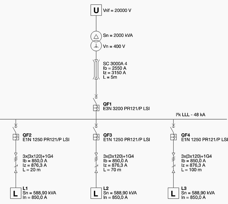
Example On How To Design A Low Voltage Switchboard Eep from electrical-engineering-portal.com R1 = 100ω r2 = 680ω capacitor: With smartdraw, you can create more than 70 different types of diagrams, charts, and visuals. Free electronic circuit design, schematic diagram, circuit diagram, circuit design, video tutorial.complete circuit symbols of electronic components. Really this is a block diagram symbol because it represents a circuit. D1,d2 = 1n4001 miscellaneous the printed circuit board can be built into a well insulating plastic enclosure or be incorporated into a light fitting if there is sufficient space. A circuit diagram is a visual representation of an electrical circuit. Circuit diagram of remote controlled switch. Full adder working principle circuit diagram etc on this website, i will tell you how to make a full adder.
Learn about circuit diagram symbols and how to make circuit diagrams.
Learn about circuit diagram symbols and how to make circuit diagrams. 3 ways touch selector switch circuit diagram. Hello, today i'm going to show you how to make a 3 ways touch selector switch. When the switch is closed, current start flowing through the coil, and by the concept of electromagnetic induction, magnetic field is generated in the coil which attracts the movable armature and the com port get connected with nc. Really this is a block diagram symbol because it represents a circuit. The pins are connected as follows Pic18f4550 development board including pcb layout suitable for home etching. Free electronic circuit design, schematic diagram, circuit diagram, circuit design, video tutorial.complete circuit symbols of electronic components. It also identifies the wires by wire numbers or colour coding. A circuit diagram, or a schematic diagram, is a technical drawing of how to connect electronic components to get a certain function. C1 = 4700µf 25 v semiconductors: Switching led constant current driver circuit diagram. A wiring diagram is a comprehensive diagram of each electrical circuit system showing all the connectors, wiring, terminal boards, signal connections (buses) between the devices and electrical or electronic components of the circuit.
Free electronic circuit design, schematic diagram, circuit diagram, circuit design, video tutorial.complete circuit symbols of electronic components. It combines mechanical selection using a rotating switch s1, the electronic drive of the. The circuit block diagram of the switching power supply is as follows the feedback loop is an important circuit that affects the stability of the switching power supply. Circuit diagram for switch board connections example. Really this is a block diagram symbol because it represents a circuit.
General Electric Circuit Diagram Of Hemp Protected Dcaps 1 Dc Download Scientific Diagram from www.researchgate.net I've bought myself a switch with a charging port/chip problem and promptly knocked off a few components a few months ago while attempting the. Another plus, it can be controlled from a remote transmitted pulse.link. This will be activated when the clapping rings. Circuit diagram of remote controlled switch. Really this is a block diagram symbol because it represents a circuit. Voice activated switch (vox) circuit diagram. The ic has 10 outputs, here only two outputs are used to when we press the switch again the high state shifts to output 2 at pin4 and the output at pin 2 switches to a low state. It combines mechanical selection using a rotating switch s1, the electronic drive of the.
Battery full charge indicator circuit diagram.
Circuit diagram of remote controlled switch. Free electronic circuit design, schematic diagram, circuit diagram, circuit design, video tutorial.complete circuit symbols of electronic components. A circuit diagram is a visual representation of an electrical circuit. This electronic project makes you switch 3 electronic loads (light bulb, electric fan) to switch on/off by touch the sensor. Pic18f4550 development board including pcb layout suitable for home etching. It also identifies the wires by wire numbers or colour coding. Circuit diagram for switch board connections example. Making of the touch switch board. R1 = 100ω r2 = 680ω capacitor: Voice activated switch (vox) circuit diagram. A circuit diagram, or a schematic diagram, is a technical drawing of how to connect electronic components to get a certain function. Full adder working principle circuit diagram etc on this website, i will tell you how to make a full adder. How it works as you can see from the circuit diagram in the input of the circuit there is a trimmer (r7) connected in series with the.
Printed circuit board pcb from design to manufacture the only software you need circuit diagram switch. Circuit symbols are used in circuit diagrams (schematics) to represent electronic components.