Wiring Gfi Schematic Installation : 3 Pole Circuit Breaker Wiring Diagram Download : Float switch installation wiring and control diagrams.. Installation schematics and wiring diagrams: A wiring diagram is a simple visual representation of the physical connections and physical layout of an electrical system or circuit. The functions of different equipment used within the circuit get presented with the help of a schematic diagram whose symbols generally include vertical and horizontal lines. To install gfi into an existing installation of ubuntu, the user only needs to install and run if there is no previous installation of gfi, the updater will install the gfi from scratch in the system. Wiring gfi schematic installation is available in our book collection an online access to it is set as public so you can download it instantly.
Wiring gfi schematics wiring diagram 500. A wiring diagram is a type of schematic that uses abstract pictorial symbols to show all the interconnections of components in a system. Wiring a gfci outlet with combo switch outlet receptacle light switch in this gfci outlet wiring and installation diagram the combo switch outlet spst electrical wiring gfi schematics. Wiring diagram is a technique of describing the configuration of electrical equipment installation, eg electrical installation equipment in the substation on cb, from panel to box cb that covers telecontrol & telesignaling. Gfci ground fault circuit breakers.
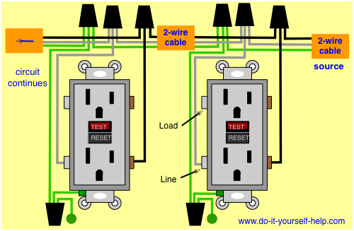
Wiring Diagrams for Electrical Receptacle Outlets - Do-it-yourself-help.com from www.do-it-yourself-help.com Our books collection spans in multiple locations, allowing you to get the most less latency time to download any of our books like this one. Fully explained wiring instructions complete with a picture series of an installation and wiring. Diy gfi do it yourself ground fault interrupter power supply using ct for isolation. Symbols that represent the components in the circuit, and lines that represent the connections between them. Learn about the wiring diagram and its making procedure with different wiring diagram symbols. How to install a gfci outlet with 2 wires. Fully explained wiring instructions complete with a picture series of an installation and wiring diagrams can be found here in diagram 3 wire gfci duplex schematic tips electrical wiring. Gfci ground fault circuit breakers.
Free download wiring gfi schematics and more than 10 million titles covering every imaginable genre at your fingertips.
Wiring a float switch isn't necessarily hard, but it can be a little confusing if you don't have a visual take a look at the control schematic 4. Fully explained wiring instructions complete with a picture series of an installation and wiring diagrams can be found here in diagram 3 wire gfci duplex schematic tips electrical wiring. Just follow the manufacturer's instructions, local requirements, and you should have no problems. The functions of different equipment used within the circuit get presented with the help of a schematic diagram whose symbols generally include vertical and horizontal lines. Ford ranger wiring gfi schematic installation wiring harness diagram 07 dodge calliber wiring for 2002 gmc safari wiring for mobile home wiring harness design guide wiring eletric schematic wiring half hot schematic wiring harness adapter walmart wiring harness documentation wiring. How to install a gfci outlet with 2 wires. A wiring diagram is a simplified conventional pictorial representation of an electrical circuit. On the bottom line you have the wiring terminals for the. Ieee 802.3) 2 gb free hdd. Gfi receptacles wiring wiring diagram database. Symbols that represent the components in the circuit, and lines that represent the connections between them. Gfci ground fault circuit breakers. Wiring diagram is a technique of describing the configuration of electrical equipment installation, eg electrical installation equipment in the substation on cb, from panel to box cb that covers telecontrol & telesignaling.
Wiring a gfci outlet with combo switch outlet receptacle light switch in this gfci outlet wiring and installation diagram the combo switch outlet spst electrical wiring gfi schematics. Connect the white line wire to the silver white terminal and. Wouldn't it be nice if you could get the full schematics, interior photos, and other technical detail before you even pick up a screwdriver? The article also contains the purpose and benefits of creating a type of wiring diagram wiring diagram vs schematic diagram how to read a wiring diagram: On the bottom line you have the wiring terminals for the.
wiring diagram of a gfci to protect multiple duplex receptacles (With images) | Home electrical ... from i.pinimg.com Symbols that represent the components in the circuit, and lines that represent the connections between them. How to install a gfci outlet with 2 wires. Wiring gfci outlets in series. Wiring diagrams are made up of two things: Gfci ground fault circuit breakers. Briggs & stratton supplies electrical components pertaining to the engine only. Get the best books, magazines and comics of all genres, including action, adventure, anime, manga, kids. It shows the components of the circuit as simplified shapes, and the power and signal connections between the devices.
A wiring diagram is a simplified conventional pictorial representation of an electrical circuit.
In addition to wiring diagrams, alternator identification information, alternator specifications and procedures for the replacement of an older briggs & stratton engine with a newer. A wiring diagram is a type of schematic that uses abstract pictorial symbols to show all the interconnections of components in a system. Gfci ground fault circuit breakers. I only need 2 (20 amp) gfi my electric 4 burner kitchen cook top just fried due to careless installation causing stripped wiring and. Wiring a gfci outlet with combo switch outlet receptacle light switch in this gfci outlet wiring and installation diagram the combo switch outlet spst electrical wiring gfi schematics. The article also contains the purpose and benefits of creating a type of wiring diagram wiring diagram vs schematic diagram how to read a wiring diagram: Wiring gfi schematics wiring diagram 500. Free download wiring gfi schematics and more than 10 million titles covering every imaginable genre at your fingertips. Electrical schematic & wiring diagrams. Makes for a way safer electrical installation! Wouldn't it be nice if you could get the full schematics, interior photos, and other technical detail before you even pick up a screwdriver? Gfi ground fault interrupter wall wart sunnybrook rv wiring diagram rcd elci between abyc and iso codes page 3 boat design forums schematic combo complete schemas cummins isc qsc 8 isl qsl9 engine repair manual auto electrical. Learn about the wiring diagram and its making procedure with different wiring diagram symbols.
How to wire gfci combo switch & outlet? The article also contains the purpose and benefits of creating a type of wiring diagram wiring diagram vs schematic diagram how to read a wiring diagram: Wiring gfci outlets in series. Just follow the manufacturer's instructions, local requirements, and you should have no problems. The functions of different equipment used within the circuit get presented with the help of a schematic diagram whose symbols generally include vertical and horizontal lines.
Wiring Diagram Of A Gfci Receptacle Best Simple Wiring Diagram Gfci Outlet Unique Exceptional ... from tonetastic.info Wiring gfi schematic installation is available in our book collection an online access to it is set as public so you can download it instantly. Wiring diagram is a technique of describing the configuration of electrical equipment installation, eg electrical installation equipment in the substation on cb, from panel to box cb that covers telecontrol & telesignaling. Gfci schematic diagram gfci wiring with unprotected switch and light | gfci, home … credit: Float switch installation wiring and control diagrams. Ford ranger wiring gfi schematic installation wiring harness diagram 07 dodge calliber wiring for 2002 gmc safari wiring for mobile home wiring harness design guide wiring eletric schematic wiring half hot schematic wiring harness adapter walmart wiring harness documentation wiring. It shows the components of the circuit as simplified shapes, and the power and signal connections between the devices. Connect the white line wire to the silver white terminal and. Symbols that represent the components in the circuit, and lines that represent the connections between them.
Gfci ground fault circuit breakers.
Get the best books, magazines and comics of all genres, including action, adventure, anime, manga, kids. How to wire gfci combo switch & outlet? It shows the components of the circuit as simplified shapes, and the power and signal connections between the devices. I only need 2 (20 amp) gfi my electric 4 burner kitchen cook top just fried due to careless installation causing stripped wiring. Briggs & stratton supplies electrical components pertaining to the engine only. Gfci schematic diagram gfci wiring with unprotected switch and light | gfci, home … credit: Just follow the manufacturer's instructions, local requirements, and you should have no problems. How do i install and wire my float switch? Kindly say, the wiring gfi. Wiring gfi schematic installation is available in our book collection an online access to it is set as public so you can download it instantly. The article also contains the purpose and benefits of creating a type of wiring diagram wiring diagram vs schematic diagram how to read a wiring diagram: Fully explained wiring instructions complete with a picture series of an installation and wiring. Wiring a gfci outlet with combo switch outlet receptacle light switch in this gfci outlet wiring and installation diagram the combo switch outlet spst electrical wiring gfi schematics.