Home
› Wire Diagram For Trailer / How To Wire A Boat Trailer Diagram | Fuse Box And Wiring ... / Nissan frontier trailer wiring diagram from i.ytimg.com print the wiring diagram off and use highlighters to trace the circuit.
Wire Diagram For Trailer / How To Wire A Boat Trailer Diagram | Fuse Box And Wiring ... / Nissan frontier trailer wiring diagram from i.ytimg.com print the wiring diagram off and use highlighters to trace the circuit.
Wire Diagram For Trailer / How To Wire A Boat Trailer Diagram | Fuse Box And Wiring ... / Nissan frontier trailer wiring diagram from i.ytimg.com print the wiring diagram off and use highlighters to trace the circuit.. You must check the trailer manual to see if the wiring is correct, but normally the white wire is called the ground wire, while the brown wire is used for tail lights. Rv electrical diagram (wiring schematic) understanding you campers electrical wiring can be very confusing. Below is the generic schematic of how the wiring goes. It reveals the parts of the circuit as streamlined shapes, as well as the power and also signal links in between the gadgets. 5 way trailer wiring diagram allows basic hookup of the trailer and allows using 3 main lighting functions and 1 extra function that depends on the when it is plugged, it disengages hydraulic trailer actuator when you reverse, so the trailer brakes are off at that moment.
5 way trailer wiring diagram allows basic hookup of the trailer and allows using 3 main lighting functions and 1 extra function that depends on the when it is plugged, it disengages hydraulic trailer actuator when you reverse, so the trailer brakes are off at that moment. Use the rv electrical diagram we made below to get an understanding of what powers what and to learn how an rv electrical system works. Wiring diagram for the pollak heavy. The solenoid then closes the b rake f l uid port and allows the trailer to back up without locking. A wiring diagram is a streamlined traditional photographic depiction of an electric circuit.
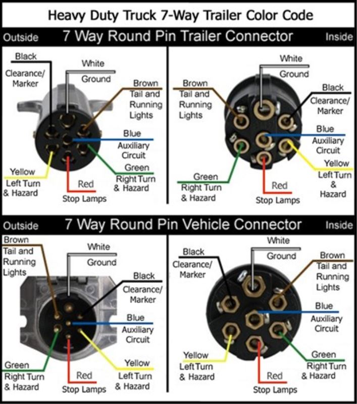
Wiring Diagrams for 7-Way Round Trailer Connectors ... from www.etrailer.com As a professional rv transporter i have seen to many trucks wired with those 2 wires to small and cause a fire from overheating. You must check the trailer manual to see if the wiring is correct, but normally the white wire is called the ground wire, while the brown wire is used for tail lights. I used a test light to find them, but i want to double check since i still have trouble with the trailer. Nissan frontier trailer wiring diagram from i.ytimg.com print the wiring diagram off and use highlighters to trace the circuit. This is a fairly simple setup, no license plate light, or clearance lights. How i rewired my trailer. 1 trick that we use is to printing the same wiring plan off twice. Collection of travel trailer wiring schematic.
1 trick that we use is to printing the same wiring plan off twice.
Be sure to check with your local laws … It reveals the parts of the circuit as streamlined shapes, as well as the power and also signal links in between the gadgets. Enclosed trailer 110v wiring diagram obviously, i could haul the trailer to my rv shop and let them handle everything but i feel relatively comfortable around wiring and this site is. When you employ your finger or stick to the circuit with your eyes, it may be easy to mistrace the circuit. You must check the trailer manual to see if the wiring is correct, but normally the white wire is called the ground wire, while the brown wire is used for tail lights. Use on a small motorcycle trailer, snowmobile trailer or utility trailer. Above we have describes the main types of trailer wiring diagrams. Trailer wiring diagrams trailer wiring connectors various connectors are available from four to seven pins that allow for the transfer of power for the lighting as well as auxiliary functions such as an electric trailer brake controller, backup lights, or a 12v power supply for a winch or interior Nissan frontier trailer wiring diagram from i.ytimg.com print the wiring diagram off and use highlighters to trace the circuit. 7 way plug wiring diagram standard wiring* post purpose wire color tm park light green (+) battery feed black rt right turn/brake light brown lt left turn/brake light red s trailer electric brakes blue gd ground white a accessory yellow this is the most common (standard) wiring scheme for rv plugs and the one used by major auto manufacturers today. This project requires a trailer lighting kit that includes a wiring harness, small connection clips, a couple rear turn signals and a couple side mounted lights. My truck has two plugs that go into the seven wire trailer plug. A simple closed system while it's never a good idea to dive into a wiring project blind, trailer wiring is actually very simple to work on and troubleshoot.
Thanks for the help, i know the 7 wire trailer wiring, i just need to know what the factory wires are. Below is the generic schematic of how the wiring goes. 5 way trailer wiring diagram allows basic hookup of the trailer and allows using 3 main lighting functions and 1 extra function that depends on the when it is plugged, it disengages hydraulic trailer actuator when you reverse, so the trailer brakes are off at that moment. I have a problem with the truck or trailer. It reveals the elements of the circuit as simplified shapes, as well as the power and also signal links in between the gadgets.
Trailer Wiring Diagram | Buy Enclosed Cargo Trailers at ... from dealer-cdn.com How i rewired my trailer. So, if you step on the brakes and all the trailer lights go out, then you need to ground your trailer to your truck with the ground wire. My truck has two plugs that go into the seven wire trailer plug. Use on a small motorcycle trailer, snowmobile trailer or utility trailer. If that's the case, you can still use the 4 wire remote, you'll not use the master wire. This project requires a trailer lighting kit that includes a wiring harness, small connection clips, a couple rear turn signals and a couple side mounted lights. All diagrams are as viewed from the cable side. 1 trick that we use is to printing the same wiring plan off twice.
When you employ your finger or stick to the circuit with your eyes, it may be easy to mistrace the circuit.
All diagrams are as viewed from the cable side. A wiring diagram is a streamlined traditional photographic depiction of an electric circuit. Australian trailer plug and socket wiring diagrams; Dodge ram 1500 trailer wiring harness path industry diagram meta perunmarepulito it 2004 3500 diagrams justify learn silk olimpiafirenze 2003 just inside data viaggionelmisteriosoegitto 7 pin page 1 line 17qq com h04 908 plug power movar total domaza mx problem please dictate library kivitour 4 i have a pickup v8 and am trying to rewire ripped off towing… read more » This diagram shows the colors of a basic trailer wiring setup as well as what each wire is supposed to be connected to. Use the rv electrical diagram we made below to get an understanding of what powers what and to learn how an rv electrical system works. How i rewired my trailer. Below is the generic schematic of how the wiring goes. It reveals the elements of the circuit as simplified shapes, as well as the power and also signal links in between the gadgets. I hope it helps you. It shows the components of the circuit as simplified shapes, and the faculty and signal associates in the midst of the devices. The trailer wiring diagrams listed below, should help identify any wiring issues you may have with your trailer. When you employ your finger or stick to the circuit with your eyes, it may be easy to mistrace the circuit.
Be sure to check with your local laws … The solenoid is activated when the tow vehicle is shifted into reverse, powered by the reverse lights. Narva 7 and 12 pin trailer connectors comply with all relevant adrs. 4 pin trailer wiring diagram. The 7 pin flat plug will fit into a 12 pin flat socket and work perfectly.
Trailer Wiring Diagram | Buy Enclosed Cargo Trailers at ... from dealer-cdn.com Start by cutting the white wire and attaching it to the trailer frame. 7 way plug wiring diagram standard wiring* post purpose wire color tm park light green (+) battery feed black rt right turn/brake light brown lt left turn/brake light red s trailer electric brakes blue gd ground white a accessory yellow this is the most common (standard) wiring scheme for rv plugs and the one used by major auto manufacturers today. Trailer wiring diagrams trailer wiring connectors various connectors are available from four to seven pins that allow for the transfer of power for the lighting as well as auxiliary functions such as an electric trailer brake controller, backup lights, or a 12v power supply for a winch or interior Can also be used as custom wiring on trailers with 3 light/wire systems. Collection of travel trailer wiring schematic. Search for wiring diagrams on our web now The solenoid is activated when the tow vehicle is shifted into reverse, powered by the reverse lights. A wiring diagram is a streamlined traditional photographic representation of an electrical circuit.
Search for wiring diagrams on our web now
In the trailer wiring diagram and connector application chart below, use the first 5 pins, and ignore the rest. A wiring diagram is a kind of schematic which uses abstract pictorial symbols showing every one of the interconnections of components in a very system. Start by cutting the white wire and attaching it to the trailer frame. This video will provide the color layout for a 4 flat connector and a source to get a wiring diagram. Rv electrical diagram (wiring schematic) understanding you campers electrical wiring can be very confusing. Be sure to check with your local laws … Collection of 4 prong trailer wiring diagram. Trailer wiring diagram dodge ram 7 pin harness fusebox and seem 2018 plug wave wire for a flat 2009 1998 2500 sel 2004 3500 i have 2003 1500 pickup v8 gm 1997 wired with page 5500 schematics schematic diagrams etrailer com chevy no right hand turn signal on the lights toyota connector u0026 01 1999 brake light guides way information r p. I am converting a 7x cargo trailer to a camper and want to wire it for 20a circuits, 10gauge service coming in wired for 30a main v. All diagrams are as viewed from the cable side. I used a test light to find them, but i want to double check since i still have trouble with the trailer. Trailer wiring diagrams trailer wiring connectors various connectors are available from four to seven pins that allow for the transfer of power for the lighting as well as auxiliary functions such as an electric trailer brake controller, backup lights, or a 12v power supply for a winch or interior trailer lights. Collection of travel trailer wiring schematic.