Resistor Wiring Diagram - Advance Ballast Wiring Diagram Resistor - Wiring Diagram Networks / Home » wiring diagram » led load resistor wiring diagram.. Home » wiring diagram » led load resistor wiring diagram. What's the difference between 4 or. Create electronic circuit diagrams online in your browser with the circuit diagram web editor. However, basic schematics of our alternator systems wired to a generic piece of. This technical article explains the ac/dc schematic representation of the protection and control systems used on power networks.
Electrical schematic & wiring diagrams. What's the difference between 4 or. Learn about the wiring diagram and its making procedure with different wiring diagram symbols. Since you can see drawing and interpreting led load resistor wiring diagram may be complicated undertaking on itself. Charger #9012 ezgo control board instructions.
Electronic Ignition Conversion-Ballast resistance - Page 2 from i50.tinypic.com Charger ezgo powerwise 1st generation wiring diagram. Wiring diagrams use simplified symbols to represent switches, lights, outlets, etc. Led load resistors wiring diagram matstrad for use with led indicator turn signal lights to make them flash at the correct. It is used along with a capacitor in. Visit the post for more. Understanding relays & wiring diagrams what is a relay and how does it work? Charger #9012 ezgo control board instructions. Home » wiring diagram » led load resistor wiring diagram.
Charger #9012 ezgo control board instructions.
A typical load resistor for a 21 watt turn signal light bulb would have a rating of 50 watts, 6 ohms. Electrical schematic & wiring diagrams. End of line resistors eols are very important for circuit and loop supervision. Electrical system ezgo resistor wiring diagram 1989 to 1994. More on peases precision resistor article edn basically it was a standard wheatstone bridge configuration which was modified to acmodate bo. Wiring and circuit diagrams 4 upon completion and review of this chapter, you should be able to: This includes ac schematics and dc schematics and diagrams. Professional schematic pdfs, wiring diagrams, and plots. Unlike a pictorial diagram, a wiring diagram uses abstract or simplified shapes and lines to show a resistor will be represented with a series of squiggles symbolizing the restriction of current flow. Relay schematics and diagrams sample wiring diagrams for a 4 pin normally open relay. However, basic schematics of our alternator systems wired to a generic piece of. The white wires are wire nutted together so they can continue the circuit. 12 volt coil with resistor wiring.
Wiring and circuit diagrams 4 upon completion and review of this chapter, you should be able to: Led turn signal load resistor wiring diagram (stop/turn signal). A wiring diagram is often made use of to repair troubles as well as to make sure that all the links motor resistor wiring diagram wire center u2022 rh 140 82 51 249 1993 chevy silverado wiring. The white wires are wire nutted together so they can continue the circuit. Briggs & stratton supplies electrical components pertaining to the engine only.
The Potentiometer And Wiring Guide - Build Electronic Circuits from www.build-electronic-circuits.com Create electronic circuit diagrams online in your browser with the circuit diagram web editor. Location of connector joining wire harness and wire harness : The white wires are wire nutted together so they can continue the circuit. Electrical interlock and dc magnet coil. Wiring and circuit diagrams 4 upon completion and review of this chapter, you should be able to: Wiring diagrams wiring diagram for outdoor lamp post wiring diagram today diy load resistors for as there s no positive or negative led resistor wiring wiring diagram pictures led resistor wiring. We suggest values between 1 kω and 4.7 kω with a power rating of 0.5 w. Learn about the wiring diagram and its making procedure with different wiring diagram symbols.
Relay schematics and diagrams sample wiring diagrams for a 4 pin normally open relay.
Farmall cub wiring diagram magneto reading industrial. Led load resistors wiring diagram matstrad for use with led indicator turn signal lights to make them flash at the correct. Electrical schematic & wiring diagrams. Understanding relays & wiring diagrams what is a relay and how does it work? You could be a service technician who wishes to look for referrals or address existing troubles. Electrical system ezgo resistor wiring diagram 1989 to 1994. However, basic schematics of our alternator systems wired to a generic piece of. More on peases precision resistor article edn basically it was a standard wheatstone bridge configuration which was modified to acmodate bo. Wiring diagrams use simplified symbols to represent switches, lights, outlets, etc. Location of connector joining wire harness and wire harness : Searching for info concerning blower motor resistor wiring diagram 1992? Basic ignition system diagram reading industrial wiring. What's the difference between 4 or.
We suggest values between 1 kω and 4.7 kω with a power rating of 0.5 w. Led load resistor wiring diagram. When you employ your finger or stick to the circuit together with your eyes, it is easy to mistrace the circuit. The white wires are wire nutted together so they can continue the circuit. Led turn signal load resistor wiring diagram (stop/turn signal).
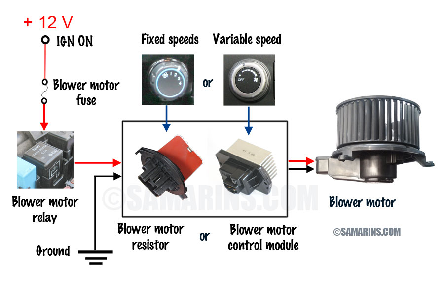
Blower motor, resistor: how it works, symptoms, problems, testing from www.samarins.com Print the wiring diagram off in addition to use highlighters to trace the routine. Wiring and circuit diagrams 4 upon completion and review of this chapter, you should be able to: Since you can see drawing and interpreting led load resistor wiring diagram may be complicated undertaking on itself. Electrical interlock and dc magnet coil. Wiring diagrams wiring diagram for outdoor lamp post wiring diagram today diy load resistors for as there s no positive or negative led resistor wiring wiring diagram pictures led resistor wiring. Electrical system ezgo resistor wiring diagram 1989 to 1994. Led load resistor wiring diagram. Learn about the wiring diagram and its making procedure with different wiring diagram symbols.
Electrical schematic & wiring diagrams.
Relay schematics and diagrams sample wiring diagrams for a 4 pin normally open relay. However, basic schematics of our alternator systems wired to a generic piece of. Visit the post for more. It is used along with a capacitor in. Unlike a pictorial diagram, a wiring diagram uses abstract or simplified shapes and lines to show a resistor will be represented with a series of squiggles symbolizing the restriction of current flow. When you employ your finger or stick to the circuit together with your eyes, it is easy to mistrace the circuit. Location of connector joining wire harness and wire harness : We suggest values between 1 kω and 4.7 kω with a power rating of 0.5 w. Basic ignition system diagram reading industrial wiring. Here is the wiring symbol legend, which is a detailed documentation of common symbols that are used in wiring. Electrical system ezgo resistor wiring diagram 1989 to 1994. Home » wiring diagram » led load resistor wiring diagram. The white wires are wire nutted together so they can continue the circuit.