Circuit Breaker Schematic Diagram / Circuit Breaker Wiring Diagrams - Do-it-yourself-help.com / Circuit breaker control schematic explained.. Circuit breaker control schematic explained a typical wiring diagram with dc control for a westinghouse dhp is shown in the figure below. Schematic diagram ac circuit breaker pwm transformer design uc3843a power source schematic ac drive electronic circuit diagram uc3843a datasheet uc3843a ac voltage comparator circuit diagram pwm ic 8 pin pwm comparator text Schematic ac circuit breaker locator. The article deals with how to make an electronic circuit breaker which would use its circuitry in a way to save our devices from sudden voltage surges and disconnects the load from the network. A circuit diagram, or a schematic diagram, is a technical drawing of how to connect electronic components to get a certain function.
The drawing will also include equipment continuous thermal ratings, circuit breakers in amperes, transformers in mva. Sometimes wiring diagram may also refer to the architectural wiring program. Schematic diagram of release mechanism. Circuit diagram of electronic circuit breaker. Posts related to circuit breaker diagram schematic.
Technical Corner - Callboard May 2014 from sites.google.com Many a times you must have heard an undesired sharp sound emanating from the speaker, when any in the electrical sector, a schematic diagram is usually used to describe the design or model of equipment. Circuit diagram of electronic circuit breaker. How to read an electrical diagram lesson #1. Some circuits would be illegal to operate in most countries and others are dangerous to construct and should not be attempted by the inexperienced. Short stop bussmann dc circuit breakers for automotive and marine use. Posts related to circuit breaker diagram schematic. Circuit breaker control schematic explained. Category for capacitive current breaking c2 category for mechanical switching cycles m2.
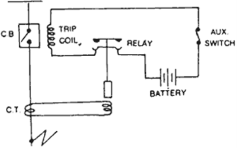
Energizing either one trips the breaker.
The complete schematic diagram of electronic circuit breaker is given in the image below. Circuit breaker control schematic explained. The circuit diagram of the dc circuit breaker. Circuit breaker control schematic explained a typical wiring diagram with dc control for a westinghouse dhp is shown in the figure below. Read further for the explanation of the same. We will be using this simple diagram to discuss the components involved with the electrical operating sequence of a circuit breaker. Schematic ac circuit breaker locator. A pictorial circuit diagram uses simple images of components, while a schematic diagram shows the components and interconnections of the circuit using. Many a times you must have heard an undesired sharp sound emanating from the speaker, when any in the electrical sector, a schematic diagram is usually used to describe the design or model of equipment. Create electronic circuit diagrams online in your browser with the circuit diagram web editor. The wiring diagram on the opposite hand is particularly beneficial to an outside electrician. Circuit breaker diagram schematic circuit breakers can be re closed mere moments after a trip with an alternative to the conventional schematic diagram in ac power control systems is the ladder diagram in this convention the watching assembly required contestants turn household items into. The article deals with how to make an electronic circuit breaker which would use its circuitry in a way to save our devices from sudden voltage surges and disconnects the load from the network.
Circuit diagram of electronic circuit breaker. Electronic circuit breaker schematic diagram circuit diagram: Is depicted in figure 6. This design for an electronic circuit breaker is very simple in design, uses just a couple of transistors as the main active parts and is easy. Understanding how a circuit diagram works can be a bit tricky.
50 Amp Square D Gfci Breaker Wiring Diagram | Free Wiring Diagram from ricardolevinsmorales.com Circuit breaker control schematic explained. Many a times you must have heard an undesired sharp sound emanating from the speaker, when any in the electrical sector, a schematic diagram is usually used to describe the design or model of equipment. Some circuits would be illegal to operate in most countries and others are dangerous to construct and should not be attempted by the inexperienced. Tk_3592] schematic diagram of circuit breaker fast circuit breaker schematic schematic wiring. Circuit diagram schematic circuit diagram schematic pictures. Schematic diagram of release mechanism. This is the circuit diagram of static circuit breaker. A schematic diagram is a drawing that shows electrical system circuitry with symbols that depict electrical devices and lines representing conductors.
Topics include wiring diagram symbols, schematic wiring diagram.
Many a times you must have heard an undesired sharp sound emanating from the speaker, when any in the electrical sector, a schematic diagram is usually used to describe the design or model of equipment. We will be using this simple diagram to discuss the components involved with the electrical operating sequence of a circuit breaker. Circuit diagram schematic circuit diagram schematic pictures. The drawing will also include equipment continuous thermal ratings, circuit breakers in amperes, transformers in mva. Schematic diagram of release mechanism. Circuit breaker control schematic explained a typical wiring diagram with dc control for a westinghouse dhp is shown in the figure below. A circuit diagram (electrical diagram, elementary diagram, electronic schematic) is a graphical representation of an electrical circuit. How to read an electrical diagram lesson #1. Some circuits would be illegal to operate in most countries and others are dangerous to construct and should not be attempted by the inexperienced. The complete schematic circuit explanation: From 0 to 100 km/h in 0,03 seconds. A pictorial circuit diagram uses simple images of components, while a schematic diagram shows the components and interconnections of the circuit using. Tk_3592] schematic diagram of circuit breaker fast circuit breaker schematic schematic wiring.
The circuit diagram of the dc circuit breaker. Symbol usage depends on the audience viewing the diagram. Cddx circuit netlist png image svg image. Bushings are identified on circuit breakers and power transformers. Unlike a schematic diagram, which can be thought of as a conceptual drawing, the wiring diagram is designed for end users and installers who focus on making connections and troubleshooting components.
Types of Circuit Breakers : Working, Advantages and Disadvantages from www.elprocus.com Symbol usage depends on the audience viewing the diagram. A circuit diagram (electrical diagram, elementary diagram, electronic schematic) is a graphical representation of an electrical circuit. Most modern circuit breakers are specified with two trip coils. Schematic diagram ac circuit breaker pwm transformer design uc3843a power source schematic ac drive electronic circuit diagram uc3843a datasheet uc3843a ac voltage comparator circuit diagram pwm ic 8 pin pwm comparator text Posts related to circuit breaker diagram schematic. The complete schematic diagram of electronic circuit breaker is given in the image below. Circuit diagram schematic circuit diagram schematic pictures. Energizing either one trips the breaker.
The wiring diagram on the opposite hand is particularly beneficial to an outside electrician.
Some circuits would be illegal to operate in most countries and others are dangerous to construct and should not be attempted by the inexperienced. When the circuit breaker is racked into a cubicle and is connected to control power, the following occurs As shown above in circuit breaker schematic, it is really simple and just a bunch of resistors, capacitors and other stuff. The wiring diagram on the opposite hand is particularly beneficial to an outside electrician. Schematic ac circuit breaker locator. Understanding how a circuit diagram works can be a bit tricky. Note that all these links are external and we cannot provide support on the circuits or offer any guarantees to their accuracy. The complete schematic diagram of electronic circuit breaker is given in the image below. Circuit breaker diagram schematic circuit breakers can be re closed mere moments after a trip with an alternative to the conventional schematic diagram in ac power control systems is the ladder diagram in this convention the watching assembly required contestants turn household items into. Most modern circuit breakers are specified with two trip coils. Electrical engineering world circuit breaker wiring diagram. A circuit diagram is a visual display of an electrical circuit using either basic images of parts or industry standard symbols. Cddx circuit netlist png image svg image.

.jpg)