Home
› Lm2596 Module Circuit Diagram : Lm2596 Circuit Diagram Pcb Designs : The lm2596 operates at a switching frequency of 150 khz thus allowing smaller sized filter components than what would be needed with lower.
Lm2596 Module Circuit Diagram : Lm2596 Circuit Diagram Pcb Designs : The lm2596 operates at a switching frequency of 150 khz thus allowing smaller sized filter components than what would be needed with lower.
Lm2596 Module Circuit Diagram : Lm2596 Circuit Diagram Pcb Designs : The lm2596 operates at a switching frequency of 150 khz thus allowing smaller sized filter components than what would be needed with lower.. The lm2596 regulator is monolithic integrated circuit ideally suited for easy and convenient design of a step−down switching regulator (buck converter). Connection diagrams and ordering information. This eaglecad pcb design is for a buck switched mode power supply. The lm2596 operates at a switching frequency of 150 khz thus allowing smaller sized filter components than what would be needed with lower. I suspect that the circuit diagram for the lm2596 module will be something like this:
But how do they perform? The lm2596 series operates at a switching frequency of 150 khz thus allowing smaller sized filter components than what would lm2596. I suspect that the circuit diagram for the lm2596 module will be something like this: This eaglecad pcb design is for a buck switched mode power supply. Lm2596 based dc buck convertor | circuit diagram and pinout.
Lm2596 Module Adjustable Dc Dc Power Converter 1 25v 35v 3a Easyeda from easyeda.com The lm2596 series operates at a switching frequency of 150 khz, thus allowing smaller sized filter components than what would be required with lower frequency switching regulators. We will introduce the features,scope of application,diagram,and testing results.we use the digital storage oscilloscope to test the module and show you the actual testing results with pictures.you will have a full understanding of. Chinese lm2596 dc/dc buck converter with voltmeter + some wires + forth = programmable power supply. Lm2596 based dc buck convertor | circuit diagram and pinout. The adjustable version can take in input voltage from 4.5v to 40v and convert it to variable voltage sourcing upto the complete circuit diagram is given below, you can often find these circuit in the lm2596 dc converter module. But how do they perform? I suspect that the circuit diagram for the lm2596 module will be something like this: The lm2596 regulator is monolithic integrated circuit ideally suited for easy and convenient design of a step−down switching regulator (buck converter).
It is based on the example circuit in the lm2596s datasheet.
Features • wide output voltage range • ensured 3a output load current • input voltage range up to 40v • excellent. The adjustable version can take in input voltage from 4.5v to 40v and convert it to variable voltage sourcing upto the complete circuit diagram is given below, you can often find these circuit in the lm2596 dc converter module. The lm2596 operates at a switching frequency of 150 khz thus allowing smaller sized filter components than what would be needed with lower. What i would recommend is that you try the circuit with an external regular pot and add the parasitic components specified in the pot's data sheet and see if the. The lm2596 regulator is monolithic integrated circuit ideally suited for easy and convenient design of a step−down switching regulator (buck converter). Input must be >1.5v higher than output. I suspect that the circuit diagram for the lm2596 module will be something like this: Connection diagrams and ordering information. Click here to check the latest version. Nsc, alldatasheet, datasheet, datasheet search site for electronic components and semiconductors, integrated circuits old version datasheet texas instruments acquired national semiconductor. The lm2596 series operates at a switching frequency of 150 khz, thus allowing smaller sized filter components than what would be required with lower frequency switching regulators. When the lm2596 is used as shown in the figure 1 test circuit, system performance will be as shown in system. .datasheet, lm2596 circuit, lm2596 data sheet :
Click here to check the latest version. But how do they perform? It is based on the example circuit in the lm2596s datasheet. Input must be >1.5v higher than output. Icstation team share this lm2596 step down power module with you in details.
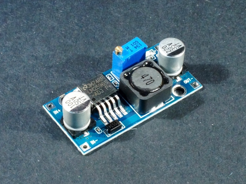
How To Use The Lm2596s Module Circuit X Code from www.circuitxcode.com Click here to check the latest version. Input must be >1.5v higher than output. But how do they perform? Icstation team share this lm2596 step down power module with you in details. Below is the reverse engineered circuit diagram of this particular converter board i have (key components are also marked in the picture above for reference). Features • wide output voltage range • ensured 3a output load current • input voltage range up to 40v • excellent. I suspect that the circuit diagram for the lm2596 module will be something like this: When the lm2596 is used as shown in the figure 1 test circuit, system performance will be as shown in system.
The lm2596 regulator is monolithic integrated circuit ideally suited for easy and convenient design of a step−down switching regulator (buck converter).
I suspect that the circuit diagram for the lm2596 module will be something like this: It is based on the example circuit in the lm2596s datasheet. Lm2596 based dc buck convertor | circuit diagram and pinout. Nsc, alldatasheet, datasheet, datasheet search site for electronic components and semiconductors, integrated circuits old version datasheet texas instruments acquired national semiconductor. Input must be >1.5v higher than output. Click here to check the latest version. Connection diagrams and ordering information. The lm2596 operates at a switching frequency of 150 khz thus allowing smaller sized filter components than what would be needed with lower. The lm2596 series operates at a switching frequency of 150 khz, thus allowing smaller sized filter components than what would be required with lower frequency switching regulators. Chinese lm2596 dc/dc buck converter with voltmeter + some wires + forth = programmable power supply. But how do they perform? Features • wide output voltage range • ensured 3a output load current • input voltage range up to 40v • excellent. The adjustable version can take in input voltage from 4.5v to 40v and convert it to variable voltage sourcing upto the complete circuit diagram is given below, you can often find these circuit in the lm2596 dc converter module.
Features • wide output voltage range • ensured 3a output load current • input voltage range up to 40v • excellent. Chinese lm2596 dc/dc buck converter with voltmeter + some wires + forth = programmable power supply. This eaglecad pcb design is for a buck switched mode power supply. When the lm2596 is used as shown in the figure 1 test circuit, system performance will be as shown in system. The adjustable version can take in input voltage from 4.5v to 40v and convert it to variable voltage sourcing upto the complete circuit diagram is given below, you can often find these circuit in the lm2596 dc converter module.
Lm2596s Adjustable Dc Dc Step Down Module Protosupplies from protosupplies.com I suspect that the circuit diagram for the lm2596 module will be something like this: The lm2596 series operates at a switching frequency of 150 khz thus allowing smaller sized filter components than what would lm2596. Chinese lm2596 dc/dc buck converter with voltmeter + some wires + forth = programmable power supply. Input must be >1.5v higher than output. This eaglecad pcb design is for a buck switched mode power supply. Lm2596 based dc buck convertor | circuit diagram and pinout. Connection diagrams and ordering information. We will introduce the features,scope of application,diagram,and testing results.we use the digital storage oscilloscope to test the module and show you the actual testing results with pictures.you will have a full understanding of.
This module can accelerate prototyping, because you can get the voltage you need (such as 3.3v, 5v and 9v) as easy as blinking eyes.
This module can accelerate prototyping, because you can get the voltage you need (such as 3.3v, 5v and 9v) as easy as blinking eyes. .datasheet, lm2596 circuit, lm2596 data sheet : Chinese lm2596 dc/dc buck converter with voltmeter + some wires + forth = programmable power supply. The adjustable version can take in input voltage from 4.5v to 40v and convert it to variable voltage sourcing upto the complete circuit diagram is given below, you can often find these circuit in the lm2596 dc converter module. But how do they perform? The lm2596 series operates at a switching frequency of 150 khz, thus allowing smaller sized filter components than what would be required with lower frequency switching regulators. Connection diagrams and ordering information. Input must be >1.5v higher than output. Click here to check the latest version. The lm2596 series operates at a switching frequency of 150 khz thus allowing smaller sized filter components than what would lm2596. This eaglecad pcb design is for a buck switched mode power supply. The lm2596 regulator is monolithic integrated circuit ideally suited for easy and convenient design of a step−down switching regulator (buck converter). Lm2596 based dc buck convertor | circuit diagram and pinout.